This blog is a repository for all my the bike-related studies over the past 20+ years. The content ranges from modelling and analytical studies, to hacks and bodges made to my bike equipment. It's all been done in an attempt to make myself faster on a bike, to make the most of my mediocre fitness.
Blog posts have been written from 2020 onwards. The dates of the posts reflect when the work was originally done.
It’s almost complete now, with just a few older posts still to write up.
Showing posts with label Hardware hacks and bodges. Show all posts
Showing posts with label Hardware hacks and bodges. Show all posts
Since buying a 3D printer at the start of the year, I've spent lots of time playing around with it, producing various things for my bikes and home. A lot of my other bike projects have been put on the back burning temporarily while I'm enjoying the world of 3D printing and creating my designs in CAD.
I've already designed and printed a flow diffuser for my indoor cycling winter setup (see blog post here) and a fan mounting bracket (see here), and I have number of other bike-related things I want to create using the 3D printer in the coming months.
My latest creation, shown in the photo above, is a handlebar mounting bracket for my Cycliq Fly12 bike camera.
The Cycliq camera came supplied with a handlebar mount, also shown in the photo above, but one of them. Since I often want to put the camera on several different bikes, I need to have several camera mounts, to avoid the need to unscrew and move the mount from bike to bike. Unfortunately, the spare handlebar mounts that Cycliq sell (see here) are quite pricey, at £22.99 each.
I'm not prepared to spend almost £100 to buy several mounts for my spare bikes. Instead, I’ve created a replica which can be 3D printed.
It works well and only uses 16g of plastic filament to produce (equivalent to about 20 pence). It requires a couple of M3 machine bolts and nuts, but that's it. It works well, and I've even created a version with a slightly ovalized radius that fits onto some of my stems.
It's free to download in case anybody has a 3D printer and wants to use it:
This trumpet-shaped object is the diffuser that I've designed and 3D printed for my indoor cycling setup. This blog post describes my reasons for doing this, how I designed it, and how the diffuser alters the airflow characteristics of the fan.
In my previous blog post I explained how my new improved indoor cycling setup now includes two Cleva Vacmaster fans. The fans are excellent, providing powerful jets of air to help keep me cool during hard workouts.
The fans have three speed settings, with the fastest #3 setting delivering a airspeed of 31 kph at the centre of the jet, at a distance of 1 metre from the nozzle. Directly in front the nozzle, the airspeed is obviously faster, 55 kph, but the measurements at 1 metre are more appropriate to how I use the fan. On its lowest #1 setting, the speeds at 1 metre are approximately 60-70% of the airspeeds at the highest setting.
Why a Diffuser?
The problem I've found is that during the colder winter months, when it's around 10 degrees Celsius in my garage, the airspeed at even the lowest fan setting is a bit too fast. This is especially true when doing easier Zone 2 endurance rides. I find that need some airflow to avoid getting sweaty, but I only need a very light breeze. With the more powerful Cleva fans I found myself often getting too cold, even with the fans on their lowest setting. I would get too sweaty when the fans were off, though, so found myself cycling them on and off.
I decided that I would try to make a diffuser. A diffuser should slow the flow down by causing it to 'spread out'. This would, if it works, also cause the jet to become broader, having the additional benefit that the flow would cover more of my body, which should be helpful at times when I wanted the fan to be on it's full setting, to keep me cool. To do that though, the diffuser would have to work properly, meaning no flow separation within the diffuser, in order to maintain full aerodynamic efficiency. If flow separations occur inside the diffuser, then aerodynamic losses occur (total pressure losses), the result of which is that the air would slow down somewhat, but the jet would not widen correctly. In that case, the same result could be achieved simply just by restricting the flow with an object that partially blocks the nozzle (e.g. a grid, or a gauze).
Diffusers are also used in a couple of other applications that people may be familiar with:
On the rear underside of Formula 1 cars, and other race cars (see here). Race car diffusers achieve the same result, slowing down the air flow by causing it to spread out, to expand. The objective is slightly different though - when the flow slows down, it increases in pressure, returning to the ambient pressure as it leaves the back of the car. This in turn allows the flow under that car to be faster, operating like a venturi, which reduces the pressure below the floor of the car to a pressure below the ambient air pressure, 'sucking' the car downwards, thereby creating aerodynamic downforce.
Diffusers are also used in wind tunnels, behind the working section, to slow down the flow, allowing slower moving airflow in the return loop of the wind tunnel, reducing losses in the wind tunnel.
Fan Diffuser Mk.1
My first diffuser design was a straight tapered device, shown in the screen shots on the left. I used the Autodesk Fusion CAD package to create the diffuser in two parts. The first part is permanently fixed to the fan and replaces the standard black nozzle on the fan, having a similar shape and fittings.
The photo below shows how the two parts fit together. The fixed part has a forward facing slot around the edge of the nozzle. The diffuser has a tapered flange which then fits into that slot.
The slot and flange connection is tight enough to stay there by itself, but for extra security I drilled a couple of small holes to secure it with 3 mm wood screws.
The next step was to see whether the diffuser worked correctly. I taped down a number of small ~30mm lengths of wool onto the inside of the diffuser to help determine the flow quality.
Wool tufts are a common type flow visualisation technique used by aerodynamicists to determine where the flow is attached to the surface or separated. Attached flow means the air is moving in the intended direction, flowing smoothly across the surface. Separated flow means the flow has broken away from the surface, causing regions of recirculation where the flow can be moving in the opposite direction, creating eddies that restrict the flow and reduce the efficiency of the diffuser.
The video below shows the that some of the wool tufts are quite stable. However, other tufts are quite active, showing that the flow is separated, or nearly separated. One tuft on the lower surface is being blown backwards, indicating it's in a region of re-circulating air caused by flow separation further upstream inside the diffuser.
Generally, the result was a bit disappointing. I measured the characteristics of the airflow downstream, just to check it (see plot on the left).
This plot confirms that the airflow speed was being slowed down, but the jet wasn't getting much wider. This is another indication that the diffuser was lacking efficiency because the flow separation in the diffuser causes losses that slow the flow down but do not cause it to spread out, meaning the mass flow rate was not being conserved because the flow through the fan was being constricted. My feeling is that the angle of divergence I chose for the nozzle was too severe, causing the adverse pressure gradients in the diffuser to be too high, prompting the flow separation.
Fan Diffuser Mk.2
As a second attempt, I decided to try a diffuser with gradually increasing divergence, combined with a lot more internal vanes to help guide the flow.
In my mind, these multiple guide vanes would operate in a similar way to how corner vane cascades work in the corners of closed return wind tunnels to efficiently turn the flow through 90 degrees (see diagram on the right).
The CAD screenshot to the left shows the external shape of the diffuser (left), along with the fixed nozzle that permanently attached to the fan. The screenshot on the right shows a cut-away cross-section, showing the shape of internal guide vanes. The diffuser required about 400-500 grams of plastic filament (PETG) to make, and it took about 12 hours to print on a Bambu Lab P1S 3D printer.The number of guide vanes made it impossible to attach fixed wool tufts inside the diffuser, so instead I used a wool tuft on the end of an old wheel spoke to inspect the flow quality.
It can be seen from the video above that the flow quality looks good, with some clear changes in flow angularity across the exit of the diffuser, showing that the flow is being turned. This was encouraging. The next step was to measure the airspeed profile. Airspeed profile measurements
I used the anemometer that I described and calibrated in a previous blog post (here) to measure the airspeed at 1 metre from the fan. I measured the airspeed at 50 mm intervals up and down the centreline of the fan jet, as shown in the photo to the left. I also checked the velocity variation to the left and right of the centreline, to ensure I was measuring the centre of the jet where the peak velocities were occurring. The airflow speeds for the three different nozzles, with the fan on the highest speed setting, are shown in the plot below.The airspeed profile below shows that the Mk.2 diffuser is doing a good job, not only in slowing the flow down, but also spreading it out too.
For the lowest fan speed setting, the airspeed profiles are progressively lower, as shown in the plot below, but the differences are otherwise more or less the same.
Conclusion
Overall, I'm really please with the diffuser. It makes a noticeable difference to the airflow on colder days. On milder winter days, I turn the fan up to setting 2 or 3 to get the necessary cooling. When the weather warms up even more, in the spring, I'll remove the diffusers altogether to maximise the airspeed. For now though, in the winter temperatures, they're working great with the fans.
Added 11/10/25: Noise Measurements
Somebody added a comment on when I published the part on MakerWorld, asking about the effect on the noise of the fan. I was curious about the noise, so made some noise measurements.
I used just a simple iphone app to measure the noise. With the phone right in front of the fan, in the middle of the jet, but 1 metre away from the fan, the noise is lower with the diffuser. Without the diffuser (just the replacement nozzle) it was 76.3 dB on the lowest setting, and 87.4 dB on the highest setting. With the diffuser, it was 61.5 dB and 76.3 dB respectively, so 10-15 dB quieter. I the decibel reduction was due to diffuser slowing down the jet, so there's less of the wind noise.
I also measured the noise outside of the jet, still 1 metre downstream from the fan, but 0.8 metre off to the side. In that case, adding the diffuser made it slightly noisier, 5.5 dB noisier on the low setting (57.5 vs 52.0 dB) and 6 dB noisier of the high setting (72.0 vs 66.0 dB).
Overall then, it not a big change, a bit quieter inside the jet due to reduced wind noise, but slightly noisier outside.
In a couple of previous blog posts I showed my indoor training setups, the first one in 2016 here, and then my improved one built in 2020 here. In the last few days I've improved it further.
With hindsight, my cooling fan setup wasn't as good as it could be. The cheap pedestal fan that I've used for the last four years couldn't provide enough flow and cooling for the warmest days or the hard workouts, although it was okay most of the time.
That has changed recently though, after I bought two Cleva centrifugal fans, after seeing some good reviews from people on the TrainerRoad Forum, who discussed UK alternatives to the Lasko fan that was highly recommended by tghe guys on the TrainerRoad podcast.
Initially, I bought a single Cleva Air Vacmaster Air Mover fan, which about £50 at the time. This was great, but it has a manual switch, so I also bought a remoted controlled plug set from Amazon for £18.99, to allow me to turn the fan on, after I warm up, about 5 minutes into the cycle. The fan speed was excellent, but the fast moving air stream was quite narrow, not broad enough to cool my whole body. Therefore I decided to buy a second fan to give me more complete body coverage.
The second Cleva fan I bought was their more expensive Vacmaster Cardio54, which I bought for £79.99. It's identical to the cheaper Air Mover, except that it has a built in remote control which is slightly better because it also allows the speed to be selected from the remote, rather than just on/off.
As shown in the photo at the top, I have mounted these two fans in two positions in front of my bike and trainer, one directed at my head/torso from above and the other directed at the lower half of my body. After some experimenting, I found this to be the best setup.
The lower fan was easy to position, and required only a small block to get the angle just right. Also, it could stay in that position and wouldn't get in the way when I'm not cycling.
The upper fan was a bit more tricky though. The fan is capable of being mounted to a standard tripod threaded attachment, or alternatively mounted onto a TV wall mount that has a VESA mount. However I didn't really want to spend more money on a TV mount, so I re-purposed the fan swing arm from my old pedestal fan, as shown in the photo on the left, using a cylindrical wooden rod as the arm. To attach the fan, I made a 3D-printed backet, using the 3D printer that I brought late last year.
I designed the bracket in Autodesk Fusion 360, which is free CAD software. I incorporated a quick release mechanism into the bracket, re-using an old QR seat post clamp that I had spare.This allows the angle to be tilted to the best angle to direct air on my head and upper body. The swing arm allows the upper fan to fold out of the way, against the wall, when not in use. I've made the bracket available to download here on MakerWorld.
I'm really pleased with the new setup. The amount of cooling is excellent, and in the colder winter months it is occasionally even too much, even on the lowest setting. On those colder days, I only turn the lower fan on. The photos below show the setup with everything in place (left), and on the right it's how it looks when everything is folded away to make more space in my garage.
I recently bought a Cleva Air Mover centrifugal fan as an upgrade to my indoor cycling setup.
It came highly recommended on several TrainerRoad forum posts (see here). Compared with my old fan, it seems to be a lot better. I wanted to measure exactly how much better it is, and this blog post describes my attempts to measure the air speed that the fan generates. As usual, it's all a bit nerdy and over-the-top, so sorry about that.
Airspeed measurement methods
I bought a cheap anemometer (an anemometer is air speed measurement device) from AliExpress for an incredibly cheap £13.05. It seemed good, but given that it was so cheap, I wanted to check its accuracy with a second source of airspeed measurement.
Having recently bought a 3D printer, I decide to make a pitot tube that I could use as a 2nd instrument to measure the air speed generated by the fan. It was quick to create in CAD (<1 hour) and printed in less than an hour.
A pitot tube is a device that measures the total pressure of the flow, by having tube that is orientated in the flow direction. When the flow enters the pitot tube is comes to rest within the tube, and when it does so the pressure will be the total pressure. Total air pressure is the ambient (static) pressure of the air plus the dynamic pressure of the moving air.
Hence, the difference between the static pressure and the total pressure is the dynamic pressure, which is a function of the air speed and the air density. Hence, but knowing the air density and the by measuring the dynamic pressure (via the difference of total and static pressures) the air speed can be obtained.
I measured the difference between static and total pressure using a device called a manometer, which is the U-shaped device shown in the sketch on the left. The manometer tube is filled with a liquid, shown in purple in the sketch, and could be any liquid such as water or mercury. I used water because it was easy and its relatively low density helped with measurement precision.
I bought a manometer from Amazon for about £20. A quick calculation in Excel allowed me to calculate the airspeed that corresponds to various manometer water height differences. I also checked how sensitive the results would be to small changes on pressure and temperature, which affects the air density.
Results
I measured the airspeed at 0.5 metres from the fan nozzle and also at 1.0 metres from the nozzle. These are distances that are representative of how far away the fan would be located from me when I'm cycling.
0.5 metre distance
The AliExpress anemometer gave a maximum airspeed, in the centre of the air stream, of 11.2 m/s. The reading fluctuated by approximately +/-0.8 m/s.
My pitot tube gave a water height difference of 8 mm in the manometer, with a manometer measurement precision of about +/-1 mm. This corresponds to an airspeed of 11.32 m/s +/- 0.8 m/s. The nature of the pitot tube and manometer meant that any air speed fluctuations are damped, although the +/-1mm manometer measurement precision results in a +/-0.8 m/s uncertainty. The two measurement sources, the pitot and the AliExpress anemometer, therefore agree very well for this 0.5 metre case.
1.0 metre distance
At a distance of 1 metre, the AliExpress anemometer gave a maximum airspeed of 8.8 m/s, with +/-1.0 m/s fluctuations.
My pitot tube gave a water height difference of 4 mm in the manometer, +/-1 mm. This corresponds to an airspeed of 8.0 m/s +/- 1.0 m/s. Again, the two measurement sources therefore agree very well at this distance of 1m, and well within their measurement precision.
Speed directly at the nozzle
The Cleva website says that the maximum airspeed of their Cardio 54 fan, which is mechanically identical to their Air Mover Fan, is 54.0 kph, 45.0 and 34.2 kph for the three speed settings. These speeds correspond to airspeeds of 15.0 m/s, 12.5 m/s and 9.5 m/s. It's highly likely that these speed quoted by Cleva are the maximum speeds, directly in front of the nozzle.
I checked the speed using the AliExpress anemometer, and that device gave speed recordings at the fan nozzle of 15.4 m/s, 12.9 m/s and 10.7 m/s for the three settings, all with a variability of about +/-0.4 m/s. These values are therefore consistent with Cleva's quoted airspeeds, and actually are slightly faster.
A couple of weekends ago I managed to damage the thread on the crank axle bolt of my XTR M9100 chainset. It was really annoying, partly because I had a bike race the next day, but mainly because I felt it start to fail at a torque that was below Shimano's recommend torque setting of 45-55 Nm. The bolt gave me that tell-tale sign of a problem, where it starts to turn more than it should, and without the resistance increasing in the way it should. This happened before my torque wrench was able to click when set to 42Nm, below the recommended torque setting.
I got a replacement bolt, but it made me wonder whether my torque wrench was badly calibrated. It's a really cheap torque wrench, a budget Silverline torque wrench, bought from Toolstation, so it's quite possible that it's badly calibrated.
Anyway, I decided to use my workbench vice and hang a weight off the torque wrench, at several torque settings, then see at what distance (moment arm) the weight has to be at to cause the torque wrench to click.
The results, plotted below, shows that my torque wrench clicks out at a slightly lower torque than indicated on the wrench. This means that it's safe, in that it won't over-torque a bolt. It means that the reason my XTR chainset bolt got threaded is a bit of a mystery, but it's probably because the Shimano bolt was faulty, rather than an issue with my torque wrench.
Like a lot of road cyclists, I really like my Garmin Varia, which I've owned for a year or two. It's been one of my best bike purchases in recent years. It gives me plenty of warning of cars approaching from behind before they become audible.
I've never liked the original Garmin mount that it came with though, which attaches to the bike seatpost using a rubber spacer and O-ring. It looks untidy and doesn't really fit properly. My seatpost has a teardrop profile, so I need to use the spacer that's shaped for aero frames, but it's not quite the same shape, and so doesn't fit properly.
This weekend I built a bespoke mount which attaches to the bike's seatpost clamp instead. My seatpost clamp uses a 8mm threaded steel cylinder into which the bolt threads into. I replaced this threaded cylinder with a 8mm diameter aluminium bar, which I drilled and tapped to create an M5 thread. Into the lower end of the bar, I attached a spare Garmin mount I had, which came from a SuperStar Components TT Garmin mount.
I'm pleased with the result. My new Varia mount feels solid and I think it looks much neater. It's also slightly lighter than the Garmin mount too, at 22g for my mount versus 40g for the original mount, which is a nice little bonus.
I read somewhere recently that when performing deadlifts, you should use a proper olympic barbell and plates, so that the bar is the appropriate height off the ground. Apparently if the bar is any lower than that, it puts excessive stress on your back.
I don't have an olympic barbell, and didn't want to spend >£100 on a new set of weights when the set I have is otherwise perfectly fine.
As you can see from the photo, I decided to instead to make a couple of riser blocks to raise my barbell to the appropriate height.
Weight plates for Olympic bars are 450mm in diameter, apparently, meaning the centre of an Olympic bar will be half that, 225mm, off the ground. My barbell set, on the other hand, has weight plates that are 310mm diameter (155mm radius), which is a difference in radii of 70mm. I therefore needed to make my riser blocks 70mm in height.
I did this with some spare timber I had, an old fence post and some plywood sheet. I used an off-cut of my turbo trainer foam mat to add a bit of cushioning on top. So it was all done without having to buy any new materials, and it took only about an hour to build.
After several prototypes, these are my homemade wind noise reduction devices that I now use on my bike helmet straps. I'm really pleased with how they work.The biggest benefit is not, surprisingly, related to actually hearing things better. Instead, the biggest benefit is actually that it never seems like you're cycling into a headwind. That alone dramatically improves how enjoyable a ride is. This blog post describes how I developed them, the four iterations of prototype I went through to get something that worked, but that didn't look too stupid.
These type of wind noise devices have been around for some time. This article published about 10 years ago by James Huang on Bike Radar describes the original Cat Ears, which I think were the first wind noise reducing devices like this. The intended benefit of reducing wind noise is to enable the rider to better hear other sounds. Personally, I've often found it difficult to hear what my riding friends are saying due to wind noise, and so back in 2018 I was keen to get a pair.
Unfortunately, when I was looking to buy some of these a few years ago, the official Cat Ears weren't sold here in the UK, only in the US. Alternatives were available though, so I bought a pair of Wind Blox devices. These were good at reducing wind noise, but I didn't like how thick in profile they were. Instead of being a fluffy material, like Cat Ears, the Wind Blox devices are a foam filled wrap that had a thickness of about 1cm. The problem I found was that the arms of my cycling glasses didn't fit over the top of them, due to their bulk. I tried putting the arms underneath the straps instead, but then the noise-reducing effect didn't work. It seemed that they needed to be flush against my face to cut out the noise.
At that point, I decided that I'd try to make a pair of Cat Ear devices myself.
Homemade Cat Ears Mk.1
This was my first attempt. I made these out of pieces of black Lycra material from a pair of worn out cycling shorts, some Velcro strips, and a piece of black fluffy faux fur material bought from HobbyCraft. The fluffy material cost a few pounds for the smallest quantify I could get, which was a 10 x 100cm piece (far more than I needed) from one of their fabic rolls. The various pieces were glued together using contact adhesive.
Although they worked well, I admit they look ridiculous. I was encouraged though, that when I tried using them on a road ride, the noise reduction worked really well. I just needed to find a way to make them smaller, so I wouldn't get funny looks from people.
Homemade Cat Ears Mk.2
I tried to find a way to attach the fluffy material directly to the helmet strap. I didn't want anything permanent though, so adhesive was out to the question. I tried using safety pins, but even small ones caused the strap to ruck up, and so the straps wouldn't lie flat against my face.
I decided to try using pairs of strong Neodymium magnets, which I bought form eBay for a few pounds. By bonding 4 magnets to the back of the fluffy material, I could then use another set of magnet on the other side of the strap to hold it in place.
In many ways this worked very well. The Mk.2 was much less obtrusive and stupid looking than the wider Mk.1, as shown in the photos of the left.
The magnets had a tendency to be attracted to their neighbours though, so the whole strip would occasionally collapse in on itself into a fluffy ball, needing the be carefully unravelled. I also had a slight concern about having strong magnet close to my temples for prolonged periods of time. A quick search on the internet about adverse effects of magnets on brain activity/health didn't reveal any known problems. However, I still felt slightly uncomfortable and decided that I didn't want to take a risk with strong magnets next to my head.
Back to the drawing board.
Homemade Cat Ears Mk.3
For my next attempt, I tried to re-use a helmet strap device that comes with most Planet X helmets.
I had a couple of these spare, lying around already, because I don't use them. They have a Velcro closure, so my hope was that it would be a simply job to bond the fluffy material to the outside.
Unfortunately, these devices were slightly padded, as shown in the photo to the left, making them slightly thicker in profile than I really wanted. Also the Velcro wasn't particularly strong, so they tended to come undone quite easily.
For these two reasons, I gave up on the Mk.3 version.
Homemade Cat Ears Mk.4
Finally, with the Mk.4, I feel now that I have a device that works well. In many ways it's very similar to the Mk.1, using the same Lycra off-cuts and Velcro.
Where it differs from the Mk.1 though, is how it wraps around the helmet strap. In this respect it works more like the Mk.3.
The sketch below shows how the Mk.4 wraps around the helmet strap, versus the Mk.1. This allows it to be no wider than the helmet strap, and therefore more discrete.
The lycra material is very thin, therefore the profile remains quite thin.
The photo below shows all of the materials that were used:
Lycra material, cut from an old worn-our pair of cycling shorts.
3M 12mm Hook and Loop Tape.
Fluffy material from Hobbycraft
Impact adhesive.
Benefits
The noise reducing benefits are quite noticeable, as also noted by James Huang when he reported on them in his article. A fair amount of wind noise remains, but what they do really well is to cut out the high frequency 'tearing' noise of the wind. What remains is a lower frequency 'whooshing' sound of the wind.
On group rides I've done, I've found it easier to hear what my friends are saying, although this is perceived improvement is admittedly rather qualitative.
The most interesting thing I discovered though, which I wasn't at all expecting, is that it's now quite difficult to tell now when I'm cycling into a headwind. I still go slower into a headwind, of of course - it doesn't change that - but I didn't realise that as cyclists we must use the volume of the wind noise to judge the airspeed, and therefore the presence of a headwind.
This improvement, never feeling like I'm cycling into a headwind, is undoubtedly the greatest benefit and one that makes any ride more pleasant - Who likes that feeling of cycling into a headwind, right?
A few months ago, Bicycle Rolling Resistance (BRR) tested the latest version of Schwalbe's Thunder Burt with the 2.25" Super Ground casing (see results here). It performed really well, narrowly beating the previous best mountain bike tyre, the 2.2" Continental Race King Protection (see results here).
As BRR said in it's conclusion: "The current generation has moved to Schwalbe's Super casings with a Super Ground and Super Race version available in several sizes. As the name suggests, the Super Race should be a bit faster than the Super Ground, while the Super Ground offers a bit more protection"
"...It looks like the Super Race version of the Thunder Burt is racking up quite a few votes and has a good chance of being tested in the near future as well."
Sadly though, the Super Race version of the Thunder Burt never made it to the top of the voting list and it expired from the list last month. I was a little disappointed by this, but I decided to buy a pair of those tyres anyway, particularly as I have an upcoming beach race in April that the Thunder Burt tread is perfect for. However, I wanted to test them first, to check how they performed against the Continental Race King Protection that I already own and have installed on the back of my MTB.
Equipment and test setup
I used my roller method for this testing, which I've described recently in previousblog posts.
The testing wasn't particularly straight-forward though, because my mountain bike doesn't have a power meter. I only have power meters on my road bike, my cyclocross/gravel bike and my time trial bike. Those are all Shimano Stages left hand crank-based power meters. My mountain bike has a SRAM GXP mountain bike chainset, so the chainset isn't at all compatible with those power meters.
My solution was to use my commuting bike instead, which has a Shimano crankset and bottom bracket, albeit a MTB chainset instead of a road chainset. Road and MTB chainsets are not compatible though, having different axle lengths and Q-factors.
This meant the chainset axle was too long for the Stages 105 left-hand crank arm that I tried to fit on it. It did fit on the hollowtech tech splined axle, both having the same diameter and splines, but it left a gap between the crank arm and the bottom bracket cups. I needed a 5-6mm spacer or washer to fill the gap. I found that a spare set of axle cartridge bearings filled the gap perfectly (see photo above). This was a bodge, but it worked really well. As a result, I got my Shimano 105 power meter successfully working on the left hand side of my Shimano SLX chainset.
A bit more faffing was required to do the testing though: I had to remove my SKS mudguards, which rubbed on the large knobbly mountain bike tyres, and I changed the pedals to my good clipless SPDs too. All in all, it took a fair amount of time before I could get started.
I chose to do the testing with a lightweight (150g) butyl inner tube, just to save the time and mess associated with a tubeless set up. Since I was interested in which tyre was fastest, this approach was fine, because both tyres would be subject to the same additional losses from having the inner tube installed. Furthermore, doing the testing with an inner tube allowed a better comparison with the BRR data, which also used a butyl inner tube for their testing, albeit a heavier-weight inner tube.
Results
The plot below show how the the two tyres compare. I had enough time to repeat the testing for the Thunder Burts, after testing the Continental Race King, to confirm that Thunder Burts really does give lower CRR numbers. Since the two blocks of testing with the Thunder Burts were before and after the testing with the Race King, then I can be fairly confident the Thunder Burts are a better tyre, despite the imperfect repeatability seen in the plot below.
The differences aren't massive, and correspond to only 2-3 Watts at 25 kph, but it's a benefit worth having. Something to be noted is that the Thunder Burts were slightly larger than the Race King, at 2.35" width versus 2.2". In addition, the Thunder Burt was brand new, whereas the Race King was one or two years old and has some Stans sealant residue on the inside. This latter point might be a source of additional losses, I'm not sure, but in any case, the purpose of this exercise was to compare these two tyres ahead of my upcoming race, so these old and used tyres are the ones I would have chosen from anyway.
Finally, it's worth noting that the agreement with Bicycle Rolling Resistance data is remarkably good at the interface of the two sets of data. However, this might be a fluke.
The previous foam tyre insert testing I did (see previous blog post here) gave some interesting and surprising results. I was expecting the foam tyre inserts to cause a small rolling resistance penalty, especially at very low tyre pressures of around 15 psi. However, they didn't. The effect of the foam tyre inserts on CRR (coefficient of rolling resistance) was within the precision of what could be measured in the test, so the effect was very small or nothing. The results are re-shown in the plot below (the green symbols versus the blue symbols).
This surprising result got me thinking about the causes. Why don't the foam tyre inserts have an effect on rolling resistance? At low tyre pressures, the compression of the foam insert at the contact patch should generate hysteretic losses that manifest themselves as additional rolling resistance. Why is that not seen? It got me thinking.
One possible explanation, and one that I mentioned at the end of my previous post, was that the ends of the inserts were (unintentionally) not connected when I did the testing, so the foam insert was 'free floating' in the tyre cavity, rather than held tight against the rim. This is a plausible explanation for an absence of any effect at higher pressures. However, I would still expect the foam insert to get compressed at 15 psi, when the tyre drop (the squish) should have been enough to compress the foam insert.
There is a second possible explanation for this observation, though, for the lack of a measurable effect of the tyre inserts. I remembered that when Vittoria launched their Air Liner Road tyre insert for road bikes, they explained that their inserts compress into the rim bead when the tyre is inflated, because the foam is closed-cell foam. The effect of the tyre pressure on the Vittoria Air Liner was demonstrated nicely in their video below:
This is the reason why the effect of the Vittoria Air Liner on tyre rolling resistance measurements was negligible when it was tested by Bicycle Rolling Resistance here. It might be the same reason why Aerocoach reached the same conclusion, but for the Tubolight Road insert in their rolling resistance testing here.
Could the same thing be happening for my gravel/cyclocross tyre inserts, that they are shrinking when the tyres are inflated? I didn't even know whether the foam inserts were constructed from closed-cell foam or not.
I decided to do an experiment to find out. The method and results are shown in the YouTube video below:
Results
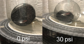
So, the answer is a YES, they do shrink, and quite a lot!
It confirms that my budget Planet X foam inserts are indeed made from closed-cell foam, and so they were subject to the same compression mechanism as the Vittoria Air Liner Road tyre insert. The picture to the left shows the cross section of the tyre insert as the pressure is raised from zero to 34 psi. At 34 psi, the insert has shrunk to about a third of it's original size. At 15 psi, it would have been approximately half it's original size.
So finally, this is plausible explanation, and the most likely reason why I saw no effect on rolling resistance when I tested at 15 psi: The tyre insert had already shrunk enough that it wasn't actually getting compressed at the tyre contact patch on the rollers.
Do tyre insert companies know this happens?
We know that Vittoria have figured this out, but what about other tyre insert companies? I'm not convinced they have.
If I look at some of the promotional pictures on the websites of the various companies selling foam tyre inserts, I get the impression they don't realise this compression is happening. For example, I have shown on the left a few pictures taken from some of the company's websites. These all show the foam tyre inserts inside the tyres rolling over objects, but the inserts are the same size and shape as their pre-inflated size.
Either the tyre insert companies don't realise what's going on, or they are trying to mislead people.
It could be argued however, that this doesn't matter, and that it's the performance of the tyre inserts that matters. I would agree with that, and the testing done by PinkBike shows that these tyre inserts do still work (for rim protection), regardless of them probably shrinking when the tyre is inflated.
However, I think it's still important to understand what size and shape the insert becomes when it's inside the inflated tyre. For example, is it still going to be wide enough to cushion and protect the rim flanks, or will the insert become too small for that, and instead get pushed down into the rim well and central channel? That will affect how impact loads are taken by the rim structure.
What many of these companies show is happening, and possibly what they thinkis happening, inside the tyre is probably not what's actually happening. It will depend on the construction of the tyre insert though, and how much air is contained in the tyre insert material. Nevertheless, what's important is to check what size and shape the insert becomes when it's inside an inflated tyre. Apart from Vittoria, I haven't seen other companies address this.
The physics behind what's happening
This final section may not be interesting to many people, but as an addendum, I can explain why a closed cell foam tyre insert shrinks when the tyre is compressed.
My foam tyre insert has a volume of around 1280 cubic centimetres and weighs 34g. That means its density is 26.6 kg per metre cubed, which shows that most of that volume is air; air inside the closed cells of the foam. In view of the density value, I would guess that more than 95% of it is air.
Before installing the tyre insert, the pressure outside and inside the foam insert is at atmospheric pressure, which is 14.7 psi at sea level. When the pressure outside of the foam insert increases, however, as happens when the tyre is inflated, that external pressure causes the air cells inside the foam to compress to the same pressure. This is the same principle as when you sit your 80kg backside on a chair: The chair and floor has to push upwards with a force of 80kg.
The volume of the air cells reduces under this increase pressure, as dictated by Boyle's law. Boyle's law says that the volume of a gas (air in this case) is inversely proportional to pressure, for a fixed mass and temperature of gas. This means that if the pressure doubles, then the volume must half.
For our particular application, a doubling of the pressure means putting 15 psi into the tyres, because remember, the pressure started at one atmosphere, which is about 15 psi.
And what happens if 15 psi is applied? The volume of the foam tyre insert approximately halves, as shown on the left. This is a good demonstration of Boyle's law. Another demonstration of Boyle's law, very similar to this, can be found here, which is the link on the Wikipedia page.
People very familiar with these gas laws may already realise that for the case rapid inflation or deflation, as shown in my video, the expansion is not strictly following Boyle's Law. This is because Boyle's law assumes an isothermal (constant temperature) expansion or compression. A rapid expansion or compression is an adiabatic process (no heat transfer) instead of an isothermal one, and is therefore subject the Ideal Gas Law instead, which considers temperature changes on pressure and volume (whereas Boyle's Law assumes temperature is fixed). In the case of a tyre being quickly inflated, if the pressure is doubled, the volume won't be halved but will be 61% instead. This 0.61 value come from 0.5 raised to the power of (1/gamma), where gamma is the specific heat ratio for air, which is 1.4.
What's important though is what volume the foam tyre insert will be when it's in the inflated tyre being ridden. In that case, the foam insert and the tyre will have reached thermal equilibrium after half an hour or so, so in all practical riding cases, where tyres would have been inflated in advance of the ride, thermal equilibrium would have been reached, and so Boyle's law is appropriate.
I've worked in the aerodynamics department of a large aircraft manufacturer for over 20 years. In my day job, I'm responsible for the prediction, modelling and measurement of the drag and lift of our aircraft. Much of my interest and knowledge of engineering and aerodynamics spills over into my main hobby, which is cycling (Road, MTB, cyclocross and time trialing).