Friday, 25 September 2026

Aerodynamic improvements for my road bike

Road bike aerodynamic improvements
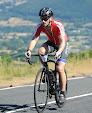
What you see to the left are the various minor modifications that I made this year to my PlanetX EC130 road bike.  I made these changes in an attempt to improve my performance at my local club 10-mile evening time trial (TT).

Most of these modifications I've designed and manufactured myself, using CAD and my 3D printer.  I've listed them all below.  At the end of this post, I've posted a few of my 10 mile TT times, showing what speed improvements I've made.

I haven't attempted to measure the improvement in CdA for any of them, simply because I haven't had the spare time or the inclination to do any Chung testing.  Instead I've just used my judgement as an aerodynamicist to decide which mods would likely make the bike faster.  That will inevitably mean that some modifications won't be as beneficial as I'd hoped, and some may be better than expected. That's just the way it is.  I've listed them in order of which modifications I perceive to be the most beneficial.

1. Deeper section wheels

Aerocoach Aeox Zephyr hub modifications
This one is the most obvious, visually, and is probably most aerodynamically beneficial.  My 'everyday' wheels are 50 mm deep carbon clinchers.  My 'fast' wheels have deeper section rims; 75 mm for the front and 85 mm for the rear.

The front wheel is an Aerocoach Aeox Zephyr wheel.  The rear is a Wiggle Prime Black wheel.  Both wheels are fitted with 25 mm Continental GP5000 tyres.  The front tyre is the slightly faster "TT" variety of the GP5000.  My thinking is that the front tyre wears out so slowly, compared with the rear tyre, that I don't mind the TT variant having a thinner tread.

One modification I've made to the front wheel is to create a small aerodynamically shaped lip for the squared-edged hub flanges, as shown above.  I don't know why Aeroocoach didn't think to do this themselves, instead of having a horrible square edge on their hub flanges.

2.  Aero bottles and aero fairing/storage

Elite Crono bottle fairings
This one took me a long time to design in CAD, and it became a bit of an ordeal to finish the design.  The biggest problem when creating 3D parts for printing is knowing the shape of the underlying geometry (i.e. the bike frame), especially when it's something having complex double curvature like a bike frame.  It needs a lot of measuring and a lot of trial and error prints.

I'm pleased with the outcome though.  What I've created is a fairing that fills in the gap between the frame and the Elite Crono CX bottles, creating a smoother, more continuous surface that should be more aerodynamically efficient.

3D printed aero frame storage
The fairing also includes a nifty storage compartment in the region below the bottles and above the bottom bracket area.  The storage compartment is large enough to hold a few essential: A spare inner tube, a multi-tool, a tyre lever, and a CO2 inflater. When it's stowed, it's held in place with strong neodymium magnets.  The video below shows how it's stowed.  This storage compartment means that I don't need to use my usual small saddle bag.  Doing away with the saddle bag is another aerodynamic and aesthetic benefit.


3. Front light and stem fairing

Aero TT light mount fairing
In the UK, front and rear lights must be fitted for any time trials.  I designed an aerodynamic front light fairing that holds my small-but-bright Moon Crescent front light.  

The fairing has the shape of leading edge of NACA 0018 aerofoil, thereby changing the cylindrical shape of the bike's head tube into a shape that's vastly superior.  It's a concept that's similar to what Specialized did with their 'speed sniffer' head tube shape on their Tarmac SL8.  Like that speed sniffer head tube, I must admit my light fairing doesn't look good, but it's functionally effective, which is the more important than aesthetics (in my opinion). The whole fairing slides onto and attaches onto a tapered spline-type of attachment that is connected to a replacement head tube spacer.  This allows the fairing to be removed easily, with just one bolt.

The head tube spacer also incorporates a fairing behind the stem, that smooths the geometry of the stem clamp, stem bolts and top cap, as shown in the photos below.

 Before:

After:

Aero aerodynamic TT time trial light mount fairing 3D printed

View from above:

Aero aerodynamic TT time trial light mount fairing 3D printed


4. Aerodynamic Garmin 840 out front mount

Garmin Edge 840 aero mount
This Garmin aerodynamic mount is a modification that I've already written about in a previous blog post (here), so I won't repeat all that again.

This should reduce the drag of the Garmin computer installation, but as with all the other modifications, it's difficult to know exactly how much benefit it creates.


5. Seatpost faring

EC130 seatpost profile
The standard seatpost on my bike is a fairly crude shape, as shown in the photo of the cross-section to the left.  The front of the seatpost had a simple cylindrical shape.  The aft section is tapered, having a kind of aerofoil-style shape, albeit a short and stumpy one.

Although the seatpost profile is aerofoil-shaped I have done some previous flow visualizations in the past to look at quality of the flow around the seatpost and the other bike tube.

Bike aerodynamics flow viz
The flow visualizations I've done (see photo to left) showed that that the flow separates at the widest part of the seatpost.  That makes the aerodynamic tail of the seatpost profile fairly ineffective at recovering the pressure and therefore the tail doesn't reduce the drag effectively.  Incidentally, I haven't yet written up that flow visualization exercise in a blog post - it's still something that's on my to-do list!

I wanted to do something to improve the shape of the seatpost, which clearly doesn't work effectively.

Seatpost aero fairing
I designed a seatpost fairing that has a more aerodynamically efficient leading edge (again, using a NACA 0018 leading edge profile).  The profile of the aft section profile that has a much more subtle taper and a 'Kammtail' truncated trailing edge.

My hope and my intent of all this fairing is that the more subtle taper will allow the flow to stay attached for longer and, just like for deep section wheels, with it's longer cross-sectional profile, the drag should reduce slightly for low cross-wind angles.  The installed seatpost fairing is shown below:


6.  Garmin Varia Mount

Garmin Varia high saddle mount
Previously I had my Garmin Varia mounted to a bracket that connected to the seatpost clamp.  That was fairly neat, but it meant the Varia - which is wider than the bike frame's seat tube - will create some extra drag I think.


Garmin Varia aero aerodynamic saddle mount 3D printed
I designed a Varia mount that instead puts the Varia up behind the saddle, which will put it in the wake of the saddle and my backside, and therefore it shouldn't create any drag.

The CAD geometry is shown on the left.  It attaches to a metal saddle mount that I use for my Cycliq rear camera.


7.  Non-bike aero mods

Rule28 leg warmers
The other big change that I made this year was to use aerodynamic leg warmers.  

The reason that I think aero leg warmers will work at the rather slow speeds I ride at (35-40kph) are explained in this previous blog post (here).  At those speeds, I think aero fabrics will reduce the drag of not only the ankle - which aero socks do - but also the calf and lower thigh.

The downside was that leg warmers combined with a long-sleeved skinsuit meant that I had no exposed skin, except for my face.  That was way too hot for many of the summer evenings this year, which additionally have been an unusually hot year in the UK.   I persevered with it though, used these for two of the four TTs, but I'm fairly sure that overheating in too much clothing was not ideal for my core body temperature and therefore my power production.

In addition to these leg warmers, I also switched from my usual road cycling shoes, which are Lake shoes having boa dials, to lace-up shoes.  Specialized tested shoes in their wind tunnel and they found that lace-up shoes are quicker by 35s over a 40km time trial.


Results

So...did all those changes make an improvement?  Yes, I did get faster, thankfully.

I only managed to do a four TTs this year.  
The first one I did was without any of these modifications, so the bike looked like the 'before' photo at the top of this post.  For the next three TTs, I had all of the modifications in place.  My times are shown below.  I want to be clear that this is a very unscientific evaluation of the modifications though, because the varying wind conditions from one week to the next has a huge influence.

  • 28th April 2026:  Low aero, moderate head wind, 27:26, 22.4 mph, 256 W avg
  • 5th May 2026:    Full aero, slight head wind, 26:05, 23.5 mph, 256 W avg
  • 23rd June 2026: Full aero except leg warmers, 25:33, 24.0 mph, 249 W avg
  • 7th July 2026:     Full aero, slight tail wind, 25:01, 24.5 mph, 258 W avg

The TT course is an 'out-and-back', but the out leg is slightly further (~6 miles) than the back leg (~4 miles) so the direction of any wind has more of an effect than for a normal out-and-back course that starts and stops in the same location.  Still, the difference in times between my first TT in April (27 minutes, 26 seconds) and my second TT (26 minutes, 5 seconds),  suggest that the modifications have made a big improvement, about a 5% improvement in speed/time. For those two TTs, there was only a small-ish change in perceived wind conditions.

For the final time trial, in which I had favorable (tail-wind) conditions, I managed to do my best time (25 minutes, 1 second) on that TT course on a road bike.

The variable wind conditions also make it impossible to accurately measure CdA from these rides.  The virtual elevation plots shown below, for the 1st, 2nd and 4th TTs, show that the virtual elevation profile 'climbs' significantly on the out leg, into the headwind, then descends on the tail wind leg.  Since the wind is affecting the CdA assessment heavily, it's often called 'apparent CdA', because it's the CdA number that appears from the analysis.  The apparent CdA numbers, 0.294, 0.264 and 0.235 are not reliable values for cases such as these that are affected so strongly by wind.  If I had a wind sensor on my bike, that would give me a better chance of getter accurately CdA values.  However, I don't, and this is one of the limitation of Chung (virtual elevation) testing, that it doesn't work well if there's a lot of wind.

To finish on a positive note though, I enjoyed the process of improving the aerodynamics of my bike.  At face value, it seems to have had the beneficial effect that I was hoping it would have on my time trial performances - an improvement of around 5% - albeit with big caveat that weather conditions varied from week to week.


Chung virtual elevation testing plot


Chung virtual elevation testing plot

Chung virtual elevation testing plot


0 comments:

Post a Comment