Thursday, 29 December 2022

Estimating my Anaerobic Work Capacity

My previous blog post showed how my critical power, how it compares to those of professional riders, and also to those of other amateur and recreational riders.

It showed that I'm relatively good at short duration efforts, less than a minute or so.  For those sort of efforts, my power numbers are in the top 2-3% of the 40-49 year-old amateur rider data stored on intervals.icu.  Furthermore, I'm actually better than the bottom 10% of professional riders (which is a nice little ego boost at this time of the year, post-Xmas, when I'm feeling fat and slow!).  I speculated that my good short duration power numbers might be a result of having a good anaerobic work capacity (AWC).  I've never analysed my AWC before, and this blog post describes a quick analysis I did to estimate my AWC.

What is Anaerobic Work Capacity?

Most serious cyclists will be familiar with functional threshold power (FTP), which is the maximum power that a rider can sustain for 60 minutes.  Riding at or just below FTP is an aerobic activity in which the build of lactate and other metabolic by-products reaches an uncomfortable but tolerable steady-state level, whereby the body is able to process lactate as quickly as it is generated by the muscles.

People will intuitively know that it's possible to cycle at powers above their FTP, but only for short periods of time.  At powers above FTP, the body is working anaerobically, because it is producing more lactate than it's able to process.  As a result, lactate and other by-products build up until they are painfully high and the rider must stop or slow down. 

The concept of Anaerobic Work Capacity (AWC), which is also called W prime or W', is that a certain amount of energy, a certain number of Joules, is available to allow a cyclist's power to exceed their person's FTP for a limited time.  AWC can be thought of as a 'battery' that has a limited number of Joules, that can be used in a number of ways.  High powers, significantly exceeding FTP (see the red rectangle in the figure above) will 'drain' the battery quickly and so can only be maintained for short periods.  Alternatively, if the power only slightly exceeds FTP (shown by the blue rectangle above), that anaerobic battery can maintain those powers for longer.  Note that the area of both red and blue rectangles is similar, because the area represents the AWC, which is calculated from the duration multiplied the the power above FTP (because power multiplied by time equals energy).

Anybody that cycles a bike will implicitly understand how these things work. You can push hard, but only for a short time, and the harder you push the shorter the time you can do that.  This AWC concept also explains the shape of a person's critical power curve, which tends to be hyperbolic, asymptoting towards their FTP value at higher durations.  At very short durations, the AWC model breaks down because a person's power will be limited by their sprint strength and their associated neuromuscular capabilities, instead of their anaerobic work capacity. This AWC concept is therefore a somewhat simplistic model of reality, but like all models it has some value.


Calculating my AWC

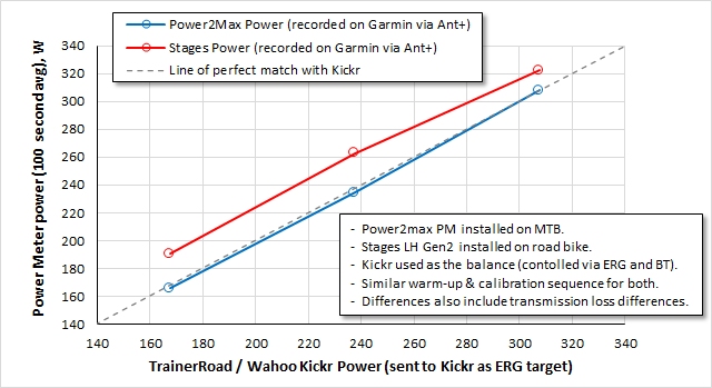
I calculated my AWC from my critical power curve that is shown by the black dashed line in the plot at the top of this post.

At each duration, I calculated the excess amount of energy, having made an assumption about my FTP.  My FTP is quite stable throughout the season and is always in the region of 275-295W.  I calculated my AWC for three FTP assumptions of 275, 285 and 295W, to get a feeling for how sensitive the results would be to that FTP assumption.

The plot below shows the results for durations ranging from 1 second to 1200 seconds (1200s is 20 minutes).  For reasons explained previously, the AWC values calculated for the very short durations, less than 30 seconds, are not valid due to the neuromuscular component of the effort that limits the power.

At the other end, the 20-minute value (1200 seconds) is not a good representation of an anaerobic effort either, because of the large aerobic contribution for that duration. However, the shape of the curves at the 10-20 minute duration gives a clue about my FTP.  The very high AWC calculated with the 275W FTP assumption suggests that 275W is too low as a value for my FTP.  It's very unlikely that I could achieve an average power of 303W for 20 minutes if my FTP was only 275W.  Similarly, the FTP of 295W seems too high when looking at the AWC values for 10 and 20 minutes when compared to the short durations.  I conclude from this that 285W is the best FTP assumption.

The AWC values for the durations of 30s, 60s and 300s are, I feel, the most reliable values.  For those durations, assuming an FTP of 285W, my AWC is around 18-20kJ.


Is my AWC any good?

It's difficult to find good data about what a 'good' AWC value is, but I thought it would be interesting to calculate the AWC for 2018 Tour De France winner Geraint Thomas.  During a 2022 podcast, Geraint mentioned that he set his best ever 1-minute power of 730W during a stage of the 2022 Tour De France.

This impressive 730W number exceeds my best 1-minute power by 111 Watts.  However, when you consider that Geraint's FTP is significantly higher than mine, probably 130-150W better, the amount of power in excess of his FTP is actually lower than I achieved.  Calculating Thomas's AWC, assuming his FTP is 420W, gives an AWC of 18.6KJ.  This is actually slightly lower than my AWC.

Before I pat myself on the back, it's worth remembering that his effort was set up a climb in the middle of a stage in the middle of a grand tour, when he wouldn't have been fresh, whereas my power records have generally been set fully rested when going for Strava KOMs.  Furthermore, we shouldn't forget that AWC in itself doesn't achieve anything, and instead it's the power that can be achieve for a certain duration that's important.


Finally...

It's also worth bearing in mind that anybody's critical power curve will be a bit lumpy, because it's created from a number of discrete efforts of different durations.  Therefore, a better estimate of your AWC is achieved by selecting the durations at which the peaks in the power curve are seen.  For me, these are the durations of my efforts up certain hills and segments when I've been going for Strava KOMs.  If I calculate my AWC values for these best durations, instead of the 'standard' 60 seconds, 300 seconds etc, my AWC numbers are even better, as shown below. 

My best AWC values, 22.9kJ @75s and 25.1kJ @146s were achieved on two memorable occasions when I went especially deep, trying to get a good time up a couple of short hill segments.  I was also very fresh when I attempted those Strava KOMs.


Wednesday, 28 December 2022

Critical power curves of professional riders (and how mine compares)

I recently came across an interesting set of data, summarised on Twitter, which contains the critical power data from 188 professional cyclists between the years of 2013 and 2021.

I'm fascinated by this kind of data.  It's interesting and humbling to see the kind of numbers that the pros produce.  Until now, the best source of data of this type that I knew of is the chart in Table 4.10 of Hunter Allen & Andrew Coggon 2010 book 'Training and Racing with a Power Meter 2nd Edition' (Ref. 1).  That chart is also readily available on the Training Peaks power profiling blog page.  However, it has always been unclear to me, at least from reading the book, what data Allen & Coggon used to create that chart.

With this new data, from Pedro L. Valenzuela et al (Ref. 2), data has been analysed from 188 cyclists (144 of them male), from 7 teams.  It contained both Pro Tour and World Tour level athletes.  Furthermore, the 144 male athletes were a mixture of all-rounders, climbers, sprinters, time triallists and GC contenders.  The data, collected from ~130,000 race and training data files, was analysed to identify the best power values at standard durations.
I don't have access to the full journal article, but the key information was already published on Twitter and also analysed on the website wattkg.com.

I have further analysed the data to compare this new data with the older chart from Allen & Coggon. I also looked at my own critical power curve to see how I compare.


My Analysis

In the chart below you can see in the three red and pink lines the new data from Pedro L. Valenzuela et al, for the 10th, 75th and 90th percentiles of the 144 male riders.  The blue symbols and the error bars show the range of W/kg values from Allen & Coggon for 'World Class' and 'Domestic Pro' categories.

It can be seen from the plot that the two sources of critical power data agree very well for 1-minute, 5-minute and 60-minute durations.  For the 5-second duration, the Allen & Coggon data shows higher W/kg values than the data from Pedro L. Valenzuela.  However, the author commented on Twitter, in reply to one of my tweets, highlighting that they had only 11 sprinters in their database as a possible explanation why his data for the 5-second critical power might seem to be relatively low.

Nevertheless, I would say that the two sources of data agree rather well.


My Power Curve versus the Pros

The dashed black curve in the chart above shows my own critical power curve, for comparison against the pros.

At the lower durations, less than a minute or so, my critical powers aren't too bad. In some cases, they actually exceed the worst pro riders (the 10th percentile pro riders).  However, at the longer durations, my lack of aerobic fitness is clearly visible, with the pro riders having critical powers approximately 30-60% better than me.  This is further illustrated in the graph below, which shows how much better, as a percentage, the pros are compared to me.

What I conclude from this is that my power over short durations is pretty good considering that I am, at best, a very mediocre amateur racer.  However, the longer durations reveal my lack of aerobic capabilities.

This probably explains why I've been able to get and hold many local Strava KOMs during the last 5-10 years, over one hundred of them, mainly on segments lasting <2 minutes, whereas I've never won a bike race of any kind!  All this suggests that I have a relatively good anaerobic work capacity (AWC).  I will analyse my AWC as a next step - something I've never done before - and write a blog post to explain my findings.


My Power Curve versus other amatuers

Finally, I want to show quickly how my power curve compares to other amateurs, because I think this shows a broadly similar picture of my strengths and weaknesses.

The website intervals.icu provides an excellent and free set of analytical tools for your cycling data files that are stored on Strava.  Furthermore, the power curve analysis page allows you to see how your critical power numbers compare to other athletes in the same demographic, showing you graphically where you sit on the 'bell-shaped curve'.  For my 40-49 age range, that's a good-sized population of around 12,000 cyclists in that age range.  The people using intervals.icu are likely to be fairly serious recreational riders and amateur riders, so that's also worth keeping in mind.

The pIot below shows that I'm at about the 80th percentile mark for my best 5-minute and 60-minute powers, but my critical powers for 1-minute and 5-second durations are much better, where I'm in the ~95th and ~98th percentiles respectively.

Again, this goes to show that my strengths are with the relatively short duration efforts. 


References

1) Hunter Allen & Andrew Coggon 2010. Training and Racing with a Power Meter 2nd Edition

2) Valenzuela PL, Muriel X, van Erp T, Mateo-March M, Gandia-Soriano A, Zabala M, Lamberts RP, Lucia A, Barranco-Gil D, Pallarés JG. The Record Power Profile of Male Professional Cyclists: Normative Values Obtained From a Large Database. Int J Sports Physiol Perform. 2022 May 1;17(5):701-710. doi: 10.1123/ijspp.2021-0263. Epub 2022 Feb 21. PMID: 35193109.


Sunday, 18 September 2022

Using virtual elevation analysis to find the fastest bike


Tomorrow I will be racing a local cyclocross race.

I pre-rode the course today on my cyclocross bike.  It's bone dry and very rough, and my feeling is that it would be quicker on my hardtail mountain bike, with its higher volume tyres. 

I wanted to properly check which bike was faster though, and I decided to check this by performing a quick Chung method virtual elevation test on the CX bike, with it's new tyres, and compare the results against the MTB, which I had tested previously.  The results, plotted above, show that the MTB is indeed fastest on the grass field that I did the testing on.

Why Chung testing?

Chung testing, also called virtual elevation (VE) testing, is a method for determining the performance of bicycle using its power meter.  It's often used by time trialists and triathletes to determine improvements to their aerodynamic efficiency, which is characterised by the CdA metric.  The method can, however, also be used to determine rolling resistance changes though, and I have performed off-road rolling resistance tests in the past using this techniques, which are documented here.

The use of the Chung method for this type of testing is that is allows one bike to be compared to another, to quickly determine the relative efficiency, regardless of whether that efficiency improvement is coming from rolling resistance, aerodynamics or weight.

The traditional way of doing an VE analysis is to iteratively adjust the parameters, either the CdA or the Crr (rolling resistance coefficient), usually using the Golden Cheetah software, until the VE profile becomes flat.  When the VE profile is flat, you know that you have a combination of CdA and Crr that is representing the performance of the bike correctly.

The alternative method, which I have used here, is to keep those parameters (CdA, Crr and weight) fixed for the analyses for both bikes, then look at the relative flatness of the two VE profiles.

In the plot above, it's clear that Bike B, the cyclocross bike, has a rising VE profile relative to Bike A, the MTB, when using the same values for CdA, Crr and weight as used for the MTB.  This rising VE profile means that the analysis 'thinks' Bike B should be climbing, because more power is needed to propel the bike than would be needed for a flat profile.  This shows that Bike B, the CX bike, is slower on the grass field I tested them on.

The beauty of this method is that it doesn't care whether the benefit is coming from rolling resistance, aerodynamics or weight.  Instead, it only shows the net results of changes to those three.  Also, as with all Chung testing, there is no need to hold a fixed power, which is a method I often see athletes and journalists trying to perform a comparative test.  The Chung method allows you to ride at whatever power you want, as long as it's reasonably similar for one test and another.

A few caveats

I should add a few caveats, because it wasn't an ideal test, performed in perfect back-to-back conditions.  Firstly the two bikes were tested on different days, so potentially the ground conditions and wind conditions were different. Qualitatively though, the ground conditions were similar on both days and although I felt there was slightly less wind for Bike B, this should favour the Bike B apparent performance.  Therefore, as Bike B is showing worse performance, it won't change the conclusion that Bike A is the best one to use.

Secondly, the two bikes had different power meters.  This not ideal, and in a perfect world I would test the same PM on both bikes.  However, I mitigated this potential bias by applying a 10W correction (10W reduction in power) to the powers from Bike B, based on comparative testing that I did previously (here and here).  All results are shown with this correction applied.  hence it would require a 16W correction for Bike B to be as fast as Bike A, and I don't think they are that far apart.

Finally, in a perfect world I would have done some repeats, like an A-B-A-B type test protocol.  However, I didn't have time.


Friday, 8 July 2022

Barbell riser blocks for deadlifts


I read somewhere recently that when performing deadlifts, you should use a proper olympic barbell and plates, so that the bar is the appropriate height off the ground.  Apparently if the bar is any lower than that, it puts excessive stress on your back.

I don't have an olympic barbell, and didn't want to spend >£100 on a new set of weights when the set I have is otherwise perfectly fine.

As you can see from the photo, I decided to instead to make a couple of riser blocks to raise my barbell to the appropriate height.

Weight plates for Olympic bars are 450mm in diameter, apparently, meaning the centre of an Olympic bar will be half that, 225mm, off the ground.  My barbell set, on the other hand, has weight plates that are 310mm diameter (155mm radius), which is a difference in radii of 70mm.  I therefore needed to make my riser blocks 70mm in height.

I did this with some spare timber I had, an old fence post and some plywood sheet.  I used an off-cut of my turbo trainer foam mat to add a bit of cushioning on top. 

So it was all done without having to buy any new materials, and it took only about an hour to build.


Wednesday, 29 June 2022

Testing MTB tyre rolling resistance using virtual elevation analysis

Mountain bike tire rolling resistance testing for optimum pressure
In a previous post from 26th April 2020, I described the rolling resistance testing that I did using my cyclocross bike, to determine the best pressure to run my tyres at, for CX races on grass.

The surprising result from that test was that there was no optimum pressure for my 35mm wide cyclocross tyres. The test instead showed that lower pressures are faster, even down to pressures that are impractically low.

Since then I've been really interested to see if the same trend holds true for other types of off-road riding, such as mountain biking.  Rolling resistance expert Tom Anhalt made an interesting comment on a Slowtwitch forum, in response to my 2020 results, saying that he remembered seeing results from the Swiss MTB Team who performed similar studies and they also concluded that lower pressure is faster.  I was keen to test this for myself, and finally had a chance to do it in June 2022.

Method

The test and analysis method I used was the same as the one that I used previously for the cyclocross tyres, described here.  There were a couple of minor differences this time:
  • I performed a repeat at only one pressure on the grass surface, whereas for the previous cyclocross tyre test, I did several off-road repeats.
  • On the other hand, I did two road tests, before and after the off-road testing, to get a feel for the repeatability of my CdA estimate.
It's also worth noting that my MTB has a spider-mounted power meter, a Power2max power meter, which measures power from both legs, whereas my Cyclocross bike had a left-hand crank-based Stages power meter.  In theory, the Power2Max power numbers should be more reliable, as it records total power properly.  In addition though, I know there are some small differences between the power measurements from my Power2Max and Stages PMs from the comparative testing that I've done previously (see here and here).  All of this means that the rolling resistance numbers aren't strictly comparable between the two bikes, the MTB and the CX bike. However, rolling resistance differences for different pressures, for the the same bike, should be reliable.

Another thing to note is that I used the same grass field for the testing as I used previously.  A grass field obviously isn't particularly representative of a typical MTB trail, but I used it mainly because:
  • There's no need to brake.  Any braking would screw up the VE analysis.
  • It's quiet and free from other riders or people getting in the way.
  • I was able to ride a consistent line around the field each time.
  • Finally, I sometimes use my MTB for cyclocross races, so I was anyway interested in the optimum MTB tyre pressures on grass.
I've thought carefully about how I could use a more representative MTB trail loop. However, I've been unable to find a suitable local trail, that allows a consistent line to be ridden, and that requires no braking etc.  This, I feel, is a fundamental problem for performance testing of mountain bikes.  Facilities like the new Vittoria testing facility offer a possibility to overcome such difficulties, and I'm looking forward to what kind of testing might be done at this facility.
 

Results

Optimum Pressure

The results shown in the plot below, which is the same plot as the one at the top of this blog post, show that the MTB tyres have a lower sensitivity of tyre pressure to rolling resistance than the CX tyres.  I would describe the MTB tyre red curve below as showing a flatter optimum, where the CRR doesn't change much between pressures of about 13 psi and 24psi.  The difference in rolling resistance across that pressure range is equivalent to less than a couple of Watts at 15 mph.  This is a convenient result, because I tend to run pressures between about 16 and 20 psi in these tyres, for comfort and grip reasons, in addition to rolling resistance considerations.  Therefore, I'll continue to run those kinds of pressures, as they seem to be best for rolling resistance too.


Other observations

Comparing the red and blue curves in the plot, for the MTB tyres and CX tyres respectively, shows that the MTB tyres are clearly faster tyres on grass, which is a conclusion I'm confident in, despite the power meter differences etc, because the difference we see there are so large.  The MTB tyre CRR values are about one third less (~40W) than for the CX tyres, which is more than the uncertainty coming from PM differences and differences in testing conditions on the day.  

The results also show that the rolling resistance of the tyres on the road doesn't change much between the two results at 34 psi and 16psi, which is a little surprising.  If I compare these data points against results of independent drum testing and my previous roller testing,  shown in the plot below, I see reasonable agreement with roller testing at the the lower pressure of 16 psi, but the 34 psi rolling resistance coefficient is much higher than the values from Bicycle Rolling Resistance obtained from their drum testing.  I can only think that this difference might be coming from higher suspension losses at 34 psi when riding the MTB over the fairly rough tarmac surface of my Aztec West road test loop.  I remember that AeroCoach's CEO Xavier Disley once said that he rarely sees long stretches of UK road surface that have a CRR less than 0.006 - and his comment was for the CRR of road tyres, not MTB tyres.  The CRR values from drum testing, which are less than 0.006 at 34 psi would not be achievable in real life based on this information from Xavier Disley, and this is my best explanation for the mismatch at 34 psi.


Monday, 25 April 2022

Homemade 'cat ear' wind noise reduction devices

After several prototypes, these are my homemade wind noise reduction devices that I now use on my bike helmet straps.  I'm really pleased with how they wo
rk. The biggest benefit is not, surprisingly, related to actually hearing things better. Instead, the biggest benefit is actually that it never seems like you're cycling into a headwind.  That alone dramatically improves how enjoyable a ride is.  This blog post describes how I developed them, the four iterations of prototype I went through to get something that worked, but that didn't look too stupid.

These type of wind noise devices have been around for some time.  This article published about 10 years ago by James Huang on Bike Radar describes the original Cat Ears, which I think were the first wind noise reducing devices like this.  The intended benefit of reducing wind noise is to enable the rider to better hear other sounds.  Personally, I've often found it difficult to hear what my riding friends are saying due to wind noise, and so back in 2018 I was keen to get a pair.

Unfortunately, when I was looking to buy some of these a few years ago, the official Cat Ears weren't sold here in the UK, only in the US.  Alternatives were available though, so I bought a pair of Wind Blox devices.  These were good at reducing wind noise, but I didn't like how thick in profile they were.  Instead of being a fluffy material, like Cat Ears, the Wind Blox devices are a foam filled wrap that had a thickness of about 1cm.  The problem I found was that the arms of my cycling glasses didn't fit over the top of them, due to their bulk.  I tried putting the arms underneath the straps instead, but then the noise-reducing effect didn't work.  It seemed that they needed to be flush against my face to cut out the noise.

At that point, I decided that I'd try to make a pair of Cat Ear devices myself.


Homemade Cat Ears Mk.1

This was my first attempt.   I made these out of pieces of black Lycra material from a pair of worn out cycling shorts, some Velcro strips, and a piece of black fluffy faux fur material bought from HobbyCraft.  The fluffy material cost a few pounds for the smallest quantify I could get, which was a 10 x 100cm piece (far more than I needed) from one of their fabic rolls.  The various pieces were glued together using contact adhesive.

Although they worked well, I admit they look ridiculous.  I was encouraged though, that when I tried using them on a road ride, the noise reduction worked really well.  I just needed to find a way to make them smaller, so I wouldn't get funny looks from people.


Homemade Cat Ears Mk.2


I tried to find a way to attach the fluffy material directly to the helmet strap.  I didn't want anything permanent though, so adhesive was out to the question. I tried using safety pins, but even small ones caused the strap to ruck up, and so the straps wouldn't lie flat against my face.

I decided to try using pairs of strong Neodymium magnets, which I bought form eBay for a few pounds.  By bonding 4 magnets to the back of the fluffy material, I could then use another set of magnet on the other side of the strap to hold it in place.

In many ways this worked very well.  The Mk.2 was much less obtrusive and stupid looking t
han the wider Mk.1, as shown in the photos of the left.

The magnets had a tendency to be attracted to their neighbours though, so the whole strip would occasionally collapse in on itself into a fluffy ball, needing the be carefully unravelled.  I also had a slight concern about having strong magnet close to my temples for prolonged periods of time.  A quick search on the internet about adverse effects of magnets on brain activity/health didn't reveal any known problems.  However, I still felt slightly uncomfortable and decided that I didn't want to take a risk with strong magnets next to my head.

Back to the drawing board.


Homemade Cat Ears Mk.3

For my next attempt, I tried to re-use a helmet strap device that comes with most Planet X helmets.

I had a couple of these spare, lying around already, because I don't use them.  They have a Velcro closure, so my hope was that it would be a simply job to bond the fluffy material to the outside.

Unfortunately, these devices were slightly padded, as shown in the photo to the left, making them slightly thicker in profile than I really wanted.  Also the Velcro wasn't particularly strong, so they tended to come undone quite easily.

For these two reasons, I gave up on the Mk.3 version.


Homemade Cat Ears Mk.4

Finally, with the Mk.4, I feel now that I have a device that works well.  In many ways it's very similar to the Mk.1, using the same Lycra off-cuts and Velcro.

Where it differs from the Mk.1 though, is how it wraps around the helmet strap.  In this respect it works more like the Mk.3.

The sketch below shows how the Mk.4 wraps around the helmet strap, versus the Mk.1.   This allows it to be no wider than the helmet strap, and therefore more discrete.

The lycra material is very thin, therefore the profile remains quite thin.


The photo below shows all of the materials that were used:

  • Lycra material, cut from an old worn-our pair of cycling shorts.
  • 3M 12mm Hook and Loop Tape.
  • Fluffy material from Hobbycraft
  • Impact adhesive.


Benefits

The noise reducing benefits are quite noticeable, as also noted by James Huang when he reported on them in his article.  A fair amount of wind noise remains, but what they do really well is to cut out the high frequency 'tearing' noise of the wind.  What remains is a lower frequency 'whooshing' sound of the wind.

On group rides I've done, I've found it easier to hear what my friends are saying, although this is perceived improvement is admittedly rather qualitative.

The most interesting thing I discovered though, which I wasn't at all expecting, is that it's now quite difficult to tell now when I'm cycling into a headwind.  I still go slower into a headwind, of  of course - it doesn't change that - but I didn't realise that as cyclists we must use the volume of the wind noise to judge the airspeed, and therefore the presence of a headwind.

This improvement, never feeling like I'm cycling into a headwind, is undoubtedly the greatest benefit and one that makes any ride more pleasant - Who likes that feeling of cycling into a headwind, right? 


Thursday, 31 March 2022

Quick and dirty cross-calibration of Stages and Power2Max power meters

I will make this a short blog post, because the chart to the left speaks for itself.

Finally, after about 4 years of  using exclusively single sided poer meters on my bikes (Stages left hand crank-based PMs), I decided to buy myself a dual-sided power meter.  This new power meter was to be fitted onto my hardtail mountain bike, a Scott Scale, which until now never had a power meter installed on it.

After some research, I decided to by a Power2max NG-eco spider-based power meter.  Strictly speaking, this measures total power, rather than both sides because the strain gauge measurements in the crank spider aren't able to differentiate whether the measured torque is coming from the left or the right side.

Before test riding my mountain bike with Power2Max power meter installed on it, I was keen to first check how its readings compared to the 2nd generation Stages power meter installed on my road bike, which I use for the majority of my training.

Unfortunately, it wasn't possible to fit both power meters on the same bike, because the the Stages Shimano 105 left hand crank arm wasn't compatible with the XTR crankset on my MTB, with the splines being different.  Instead, I used a technique I've used previously (described here) to compare power meters, whereby I used my Wahoo Kickr trainer as the 'balance'.

The method involves testing one bike, then the other, on the Kickr, with the Kickr target (ERG) power profile controlled via an app using Bluetooth, in my case the TrainerRoad app.  The actual power meter measurements are then recorded via ANT+ on my Garmin head unit.

The plot to the left shows the power meter readings versus time for the same Wahoo Kickr power profile.

It's clear that the Stages power meter reads significantly higher that the Wahoo Kickr power, whereas the Power2max power meter tracks very closely with the Wahoo Kickr.  The plot at the top of the page shows the average power over 100 seconds for each interval.  The Stages power meter reads between 15-25 Watts higher than the Kickr (5-14%), whereas the Power2max power meter is within 2-3 Watts.

There's no way to say for sure which power measurement is closest to 'the truth', but given that two power measurements match very well and the odd one out is a single-sided power meter, I think it's highly likely that the Stages power meter is the wrong one out of the three.

I think it's most likely that my left/right leg balance isn't 50/50, which is an assumption that the Stages power meter makes in it's calculation of total power from the left-hand power measurement.  A leg/right balance of 55/45, for example, would result in a 10% over-estimation of power by the Stages. 


Wednesday, 16 March 2022

Testing Schwalbe's Super Race Thunder Burts

Schwalbe Thunder Burt Super Race versus Continental Race King Protection rolling resistance
A few months ago, Bicycle Rolling Resistance (BRR) tested the latest version of Schwalbe's Thunder Burt with the 2.25" Super Ground casing (see results here).  It performed really well, narrowly beating the previous best mountain bike tyre, the 2.2" Continental Race King Protection (see results here).

As BRR said in it's conclusion: "The current generation has moved to Schwalbe's Super casings with a Super Ground and Super Race version available in several sizes. As the name suggests, the Super Race should be a bit faster than the Super Ground, while the Super Ground offers a bit more protection"

"...It looks like the Super Race version of the Thunder Burt is racking up quite a few votes and has a good chance of being tested in the near future as well."

Sadly though, the Super Race version of the Thunder Burt never made it to the top of the voting list and it expired from the list last month.  I was a little disappointed by this, but I decided to buy a pair of those tyres anyway, particularly as I have an upcoming beach race in April that the Thunder Burt tread is perfect for.  However, I wanted to test them first, to check how they performed against the Continental Race King Protection that I already own and have installed on the back of my MTB.


Equipment and test setup

I used my roller method for this testing, which I've described recently in previous blog posts.

The testing wasn't particularly straight-forward though, because my mountain bike doesn't have a power meter.  I only have power meters on my road bike, my cyclocross/gravel bike and my time trial bike.  Those are all Shimano Stages left hand crank-based power meters.  My mountain bike has a SRAM GXP mountain bike chainset, so the chainset isn't at all compatible with those power meters.


Shimano 105 Stages power meter on a Shimano SLX mountain bike (MTB) crankset
My solution was to use my commuting bike instead, which has a Shimano crankset and bottom bracket, albeit a MTB chainset instead of a road chainset.  Road and MTB chainsets are not compatible though, having different axle lengths and Q-factors.

This meant the chainset axle was too long for the Stages 105 left-hand crank arm that I tried to fit on it.  It did fit on the hollowtech tech splined axle, both having the same diameter and splines, but it left a gap between the crank arm and the bottom bracket cups.  I needed a 5-6mm spacer or washer to fill the gap.  I found that a spare set of axle cartridge bearings filled the gap perfectly (see photo above).  This was a bodge, but it worked really well.  As a result, I got my Shimano 105 power meter successfully working on the left hand side of my Shimano SLX chainset.

A bit more faffing was required to do the testing though: I had to remove my SKS mudguards, which rubbed on the large knobbly mountain bike tyres, and I changed the pedals to my good clipless SPDs too.  All in all, it took a fair amount of time before I could get started.

I chose to do the testing with a lightweight (150g) butyl inner tube, just to save the time and mess associated with a tubeless set up.  Since I was interested in which tyre was fastest, this approach was fine, because both tyres would be subject to the same additional losses from having the inner tube installed.  Furthermore, doing the testing with an inner tube allowed a better comparison with the BRR data, which also used a butyl inner tube for their testing, albeit a heavier-weight inner tube.


Results

The plot below show how the the two tyres compare.  I had enough time to repeat the testing for the Thunder Burts, after testing the Continental Race King, to confirm that Thunder Burts really does give lower CRR numbers.  Since the two blocks of testing with the Thunder Burts were before and after the testing with the Race King, then I can be fairly confident the Thunder Burts are a better tyre, despite the imperfect repeatability seen in the plot below. 


The differences aren't massive, and correspond to only 2-3 Watts at 25 kph, but it's a benefit worth having.  Something to be noted is that the Thunder Burts were slightly larger than the Race King, at 2.35" width versus 2.2".  In addition, the Thunder Burt was brand new, whereas the Race King was one or two years old and has some Stans sealant residue on the inside.  This latter point might be a source of additional losses, I'm not sure, but in any case, the purpose of this exercise was to compare these two tyres ahead of my upcoming race, so these old and used tyres are the ones I would have chosen from anyway.

Finally, it's worth noting that the agreement with Bicycle Rolling Resistance data is remarkably good at the interface of the two sets of data.  However, this might be a fluke.


Monday, 14 March 2022

Do foam tyre inserts get smaller when tyres are inflated?

Compression of MTB / gravel / cyclocross foam tyre inserts when inflated
The previous foam tyre insert testing I did (see previous blog post here) gave some interesting and surprising results.  
I was expecting the foam tyre inserts to cause a small rolling resistance penalty, especially at very low tyre pressures of around 15 psi. However, they didn't.  The effect of the foam tyre inserts on CRR (coefficient of rolling resistance) was within the precision of what could be measured in the test, so the effect was very small or nothing.  The results are re-shown in the plot below (the green symbols versus the blue symbols). 

This surprising result got me thinking about the causes.  Why don't the foam tyre inserts have an effect on rolling resistance?  At low tyre pressures, the compression of the foam insert at the contact patch should generate hysteretic losses that manifest themselves as additional rolling resistance. Why is that not seen?  It got me thinking.

One possible explanation, and one that I mentioned at the end of my previous post, was that the ends of the inserts were (unintentionally) not connected when I did the testing, so the foam insert was 'free floating' in the tyre cavity, rather than held tight against the rim.  This is a plausible explanation for an absence of any effect at higher pressures.  However, I would still expect the foam insert to get compressed at 15 psi, when the tyre drop (the squish) should have been enough to compress the foam insert.

There is a second possible explanation for this observation, though, for the lack of a measurable effect of the tyre inserts.  I remembered that when Vittoria launched their Air Liner Road tyre insert for road bikes, they explained that their inserts compress into the rim bead when the tyre is inflated, because the foam is closed-cell foam.  The effect of the tyre pressure on the Vittoria Air Liner was demonstrated nicely in their video below:


This is the reason why the effect of the Vittoria Air Liner on tyre rolling resistance measurements was negligible when it was tested by Bicycle Rolling Resistance here.  It might be the same reason why Aerocoach reached the same conclusion, but for the Tubolight Road insert in their rolling resistance testing here.

Could the same thing be happening for my gravel/cyclocross tyre inserts, that they are shrinking when the tyres are inflated?  I didn't even know whether the foam inserts were constructed from closed-cell foam or not.

I decided to do an experiment to find out.  The method and results are shown in the YouTube video below:


Results


So, the answer is a YES, they do shrink, and quite a lot!

It confirms that my budget Planet X foam inserts are indeed made from closed-cell foam, and so they were subject to the same compression mechanism as the Vittoria Air Liner Road tyre insert.  The picture to the left shows the cross section of the tyre insert as the pressure is raised from zero to 34 psi.  At 34 psi, the insert has shrunk to about a third of it's original size.  At 15 psi, it would have been approximately half it's original size.

So finally, this is plausible explanation, and the most likely reason why I saw no effect on rolling resistance when I tested at 15 psi:  The tyre insert had already shrunk enough that it wasn't actually getting compressed at the tyre contact patch on the rollers. 


Do tyre insert companies know this happens?

We know that Vittoria have figured this out, but what about other tyre insert companies?  I'm not convinced they have.

If I look at some of the promotional pictures on the websites of the various companies selling foam tyre inserts, I get the impression they don't realise this compression is happening.  For example, I have shown on the left a few pictures taken from some of the company's websites. These all show the foam tyre inserts inside the tyres rolling over objects, but the inserts are the same size and shape as their pre-inflated size.

Either the tyre insert companies don't realise what's going on, or they are trying to mislead people.

It could be argued however, that this doesn't matter, and that it's the performance of the tyre inserts that matters.  I would agree with that, and the testing done by PinkBike shows that these tyre inserts do still work (for rim protection), regardless of them probably shrinking when the tyre is inflated.  
However, I think it's still important to understand what size and shape the insert becomes when it's inside the inflated tyre.  For example, is it still going to be wide enough to cushion and protect the rim flanks, or will the insert become too small for that, and instead get pushed down into the rim well and central channel?  That will affect how impact loads are taken by the rim structure.

What many of these companies show is happening, and possibly what they think is happening, inside the tyre is probably not what's actually happening.  It will depend on the construction of the tyre insert though, and how much air is contained in the tyre insert material.  Nevertheless, what's important is to check what size and shape the insert becomes when it's inside an inflated tyre.  Apart from Vittoria, I haven't seen other companies address this.


The physics behind what's happening

This final section may not be interesting to many people, but as an addendum, I can explain why a closed cell foam tyre insert shrinks when the tyre is compressed.

My foam tyre insert has a volume of around 1280 cubic centimetres and weighs 34g.  That means its density is 26.6 kg per metre cubed, which shows that most of that volume is air; air inside the closed cells of the foam.  In view of the density value, I would guess that more than 95% of it is air.

Before installing the tyre insert, the pressure outside and inside the foam insert is at atmospheric pressure, which is 14.7 psi at sea level.  When the pressure outside of the foam insert increases, however, as happens when the tyre is inflated, that external pressure causes the air cells inside the foam to compress to the same pressure.  This is the same principle as when you sit your 80kg backside on a chair: The chair and floor has to push upwards with a force of 80kg.

The volume of the air cells reduces under this increase pressure, as dictated by Boyle's law. Boyle's law says that the volume of a gas (air in this case) is inversely proportional to pressure, for a fixed mass and temperature of gas.  This means that if the pressure doubles, then the volume must half.

For our particular application, a doubling of the pressure means putting 15 psi into the tyres, because remember, the pressure started at one atmosphere, which is about 15 psi.

And what happens if 15 psi is applied?  The volume of the foam tyre insert approximately halves, as shown on the left.  This is a good demonstration of Boyle's law.  Another demonstration of Boyle's law, very similar to this, can be found here, which is the link on the Wikipedia page.

People very familiar with these gas laws may already realise that for the case rapid inflation or deflation, as shown in my video, the expansion is not strictly following Boyle's Law.  This is because Boyle's law assumes an isothermal (constant temperature) expansion or compression.  A rapid expansion or compression is an adiabatic process (no heat transfer) instead of an isothermal one, and is therefore subject the Ideal Gas Law instead, which considers temperature changes on pressure and volume (whereas Boyle's Law assumes temperature is fixed).  In the case of a tyre being quickly inflated, if the pressure is doubled, the volume won't be halved but will be 61% instead. This 0.61 value come from 0.5 raised to the power of (1/gamma), where gamma is the specific heat ratio for air, which is 1.4.

What's important though is what volume the foam tyre insert will be when it's in the inflated tyre being ridden.  In that case, the foam insert and the tyre will have reached thermal equilibrium after half an hour or so, so in all practical riding cases, where tyres would have been inflated in advance of the ride, thermal equilibrium would have been reached, and so Boyle's law is appropriate.